I had originally intended this post to be a tutorial on initializing Direct3D 11 and rendering a triangle to the screen. Unfortunately, by the time I got past the basic theory behind utilizing Direct3D and resources this post was already 3600 words in length. If I included all of the code snippets and code explanations this post would simply be too long for a single topic. Therefore, I am going to limit this post to purely theory on Direct3D 11 operation, resources, resource views and the Swapchain.
Intended Audience
Although this post is only theory, I am creating it as part of a series so I will have the same prerequisites as my last post. Please check that you have the required knowledge, hardware, and software to continue on.
High Level Overview
Direct3D and DXGI
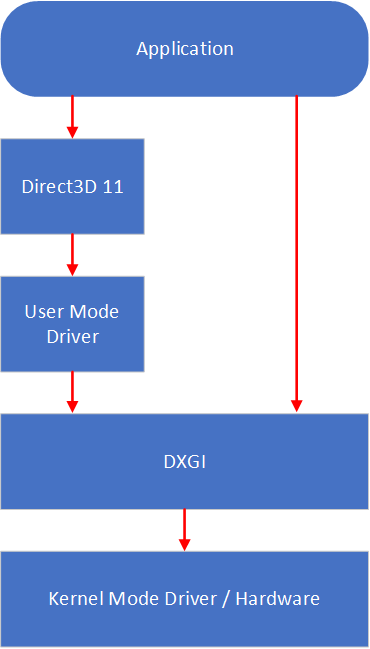
Direct3D is a native API present on Windows for communicating with and controlling video hardware. The meaning of native is that it is designed to be utilized from within a C/C++ application. Although it may seem like there is only one layer between our application and the graphics driver/hardware, there are actually numerous layers that comprise a graphics application. At the top level of this software stack is our application, this is responsible for sending data and commands to the Direct3D runtime. From there the runtime forwards those commands to the user mode driver of the video hardware which then interacts with DXGI.
DXGI or the DirectX Graphics Infrastructure is responsible for the low level communication with the kernel mode driver. Additionally, it handles the management of hardware resources related to the GPU. DXGI also has functionality that we can call directly from our application, some of this functionality can perform actions such as enumerate the video hardware present on the system and query their capabilities. It also helps us to create frame buffers called Swapchains, they allow us to present to the window.
COM
Both Direct3D and DXGI are implemented as a collection of Component Object Model (COM) interfaces. We can't go too deep into COM itself as that's out of scope and a discussion on its own. But the gist of COM is that it provides a set of standard interfaces for each object.
Each object isn't allocated through keywords like 'new'; rather, they're produced by a method that implements a factory pattern. Likewise, we cannot use 'delete' with COM objects since we never allocated them. When we utilize one of these factory methods they return a reference to you. Each COM object is reference counted, this is subsequently used to manage their lifetime.
Another important note that we need to know for COM objects is interface querying. This is part of the IUnkown interface which allows us to discover additional interfaces that a COM object implements. By passing a Universally Unique Identifier (UUID) of our desired interface, and a pointer to pointer of the desired interface reference to IUnkown::QueryInterface() we can retrieve the desired interface if it is available.
The Graphics Pipeline
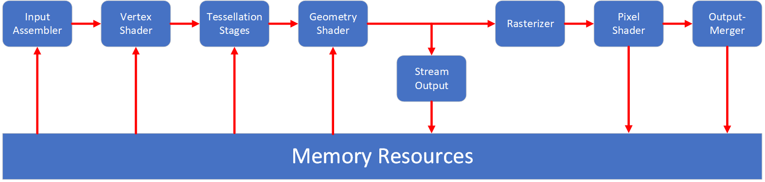
The graphics pipeline is a conceptual model for the steps/stages that are performed on input data before being written to an output buffer. (Which may or may not be the display.) Its a mixture of fixed function and programmable stages. The programmable stages of the pipeline are known as shaders. If you're into video games you've probably heard that term before. Shaders are essentially small programs that execute on a set of data. Each shader stage operates on different type of data such as vertices or pixels. Additionally, not all programmable stages need to be used. Fixed function stages are usually configurable and are sometimes a dedicated piece of hardware on the GPU. They perform only one function and are usually configured through and exposed state. The graphics pipeline is manipulated through what is called a device context. It is encapsulated through the ID3D11DeviceContext interface, this interface provides methods to update the state of the pipeline by setting resources, shaders, and various state objects for the fixed function stages of the pipeline.
Input Asssembler
The Input Assembler stage is a configurable fixed function stage that assembles primitive data (points, lines, triangles) from user-filled buffers into primitives types such as point lists, line lists, triangle lists, triangle strips and numerous other types. Several types contain adjacency data that can be used later on in the pipeline. This stage also attaches system-generated values to primitives to increase the efficiency of shaders. These values are referred to as semantics. The buffers that we bind to the stage contain per-vertex data. In this stage we need to create what's called an input layout that describes the data elements in the buffer. This input layout is dependent on what the vertex shader expects in the next stage.
Vertex Shader
The Vertex Shader is a programmable stage that processes vertices from the input assembler by performing per vertex operations like transformations or per-vertex lighting. These shader programs always operate on only one vertex at a time. This stage is always active and as such, if it's not needed, it must be programmed to pass through the data. Vertex shaders are encapsulated by the ID3D11VertexShader interface.
Tessellation Stages
Although the image above only shows one stage, in reality this actually three separate stages. The three stages are the Hull Shader, Tessellator, and Domain Shader. These stages are designed for surface subdivision, essentially what this means is it will take a the polygons that make up a surface and divide them. This yields a higher fidelity surface that before with a less faceted appearance. We're only glossing over these stages as they're fairly advanced and technical.
Geometry Shader
The Geometry Shader is designed to generate new vertices using the adjacency data of some primitive types mentioned earlier in the Input Assembler stage. Again, this is also an advanced topic that is out of scope for this post. Geometry shaders are encapsulated by the ID3D11GeometryShader interface.
Stream Output
The Stream Output stage is fairly simple, it's designed to output processed primitives before they're rasterized (transformed into pixels). This can be useful when you're utilizing multi-pass rendering techniques. This simply means that data is processed in the pipeline and then streamed out, the pipeline will then be reconfigured before that data is sent back into the pipeline for further processing.
Rasterizer
The Rasterizer is a configurable fixed function stage that takes our primitives and turns them into raster images (pixel images). This stage also performs functions such as culling and clipping (removing hidden pixels). This stage can also be configured to change the "fill" of rendered primitives. For example, this stage can be configured to rasterize primitives as wireframes.
Pixel Shader
The Pixel Shader is a programmable stage that is extremely powerful as it allows us to perform techniques like per-pixel lighting, texturing and post processing. It takes in a variety of data like constant variables and texture data to produce per-pixel outputs. The Rasterizer stage invokes the pixel shader once for each pixel covered by a primitive. Pixel shaders are encapsulated by the ID3D11PixelShader interface.
Output-Merger
The Output-Merger stage is the last step in the pipeline. It's a fixed function stage that assembles all our pixels into a cohesive image. It can utilize depth data of each pixel to determine which pixels are present (unobstructed) in the final image.
Direct3D Resources
There are generally two groups of resources found within Direct3D, Textures and Buffers. Textures are a roughly split into one, two and three dimension textures; whereas, Buffers are more uniform and are generally considered to be one dimension. Buffers have numerous different types corresponding to the type of data they hold and/or how they're utilized. Both groups of resources are bound to various points throughout the graphics pipeline. All resources, state objects and shader objects found within Direct3D are created through what is called the Device. This is related the device context that we discussed earlier. The Device is encapsulated by the ID3D11Device interface, every Direct3D application must have at least one device (though they usually only have one).
Textures
Textures are a structured collection of elements known as texels. You can think of them as a series of cells in a cartesian coordinate system. Normally we would denote the axes as X, Y and Z, but because those are already used in model/world/camera space (coordinates of objects in a virtual world) we refer to them as U, V and W. They refer to the length, width, and depth respectively (if applicable). Textures are most commonly seen in their two dimensional form as they're often used to detail a 3D model using a bitmap image. You can see this in the image down below, the first tank is untextured where as the second tank is textured. (Image credit to Wikipedia.) It should be noted though that textures can contain more than just color information, one example is that they're often used to store depth information.
1D Textures
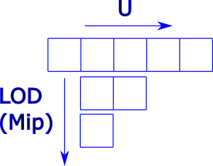
As the name implies, this type of texture is one dimensional. Its probably easiest to think of these as an array of colours. Depending on the data format each texel can contain a number of different colour components. These textures are addressed using the U coordinate. These textures are encapsulated by the ID3D11Texture1D interface.
2D Textures
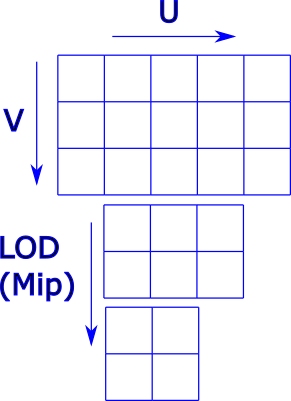
Much like a regular image . This is a two dimensional texture that can represents a 2D bitmap image. These are addressed by the U and V coordinates and are utilized in a process called UV mapping. These textures are encapsulated by the ID3D11Texture2D interface.
3D Textures
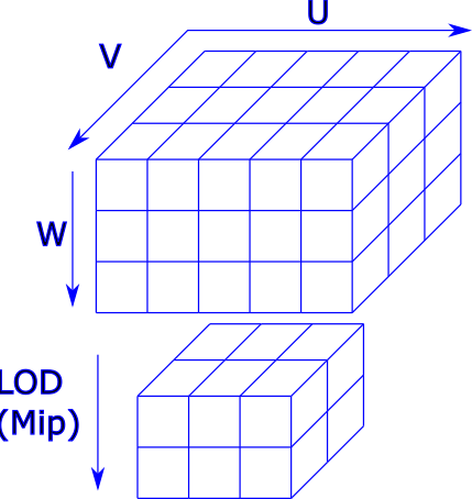
You can visualize these textures as a cube that is addressed by the U, V, and W coordinates. These are frankly quite weird, but they can be used for really cool effects like volumetric smoke or volumetric light rays. These textures are encapsulated by the ID3D11Texture3D interface.
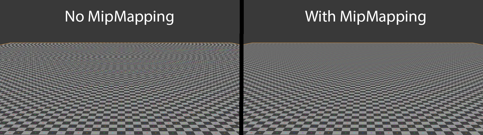
Mipmaps
Mipmaps are progressively lower resolution textures that are calculated from a texture resource and stored along with it. Usually multiple mip 'levels' exist which are progressively smaller textures. Mipmaps are used to increase rendering speed and aliasing artifacts. They're often used for far away objects in a scene since at longer ranges only so much detail can be seen on an object. You can see the effect of mipmapping in the image below. Notice the banding towards the top of the image. (Image credit to Wikipedia.) Each texture resource you create has the ability to store mipmaps of it self.
Texture Arrays
Both ID3D11Texture1D and ID3D11Texture2D are capable of containing homogenous arrays. By homogenous, I mean that each texture of the array has the same data format, dimensions, and mip levels.
Buffers
Buffers are an unstructured resource that are a collection of of typed data groups. They can store numerous forms of data including, but not limited to: positional vectors, texture coordinates, indices. Because they're unstructured, they cannot contain mipmap levels. There are six different types of buffers in Direct3D 11, all of them are encapsulated through the ID3D11Buffer interface. In this post we're going to focus only on a the vertex, index, constant buffers. The others which are the structured buffer, append and consume buffer, and finally the byte address buffer. These last three buffer types are bit more advanced so we're going to skip over them for now.
Vertex Buffers
Vertex buffers are buffers that are designed to hold contain per vertex data. This data can vary wildly depending on what your pipeline configuration is expecting. For example, here is a vertex definition for the program that I will go over in the next post.
Here you see that each one of my vertices are comprised of two, four float packs. One pack for the position of the vertex and one pack for RGBA colour. The array specifies three vertices that make up a triangle. That array would be memory copied to the GPU upon creating the buffer.
Index Buffers
Index buffers are related to vertex buffers, they store indices that determine which vertices make up a primitive. Indices are represented as an array of either 16bit or 32bit unsigned integers. Technically, you don't need to use index buffers at all, this is because there are draw calls that simply use the order of the vertices for creating primitives; however, this creates the problem that you need to duplicate vertex data in a model as vertices can't be shared. Consider a cube, in total there a total of twelve triangle primitives that comprise it (two per face). If we used indexed rendering then we only need eight vertices to represent a cube. But if we used vertex order based rendering we would need a total of 36 vertices to draw a cube. This is because each triangle primitive would need 3 vertices in order to be drawn.
Constant Buffers
Constant buffers are unique in that they're designed to supply a shader program data constants. A common use case of constant buffers is the transformational data used in vertex shaders. This would be comprised of a matrix or matrices that transform the vertices within a model to a new position.
Resource Usage and CPU Access
Both textures and buffers have the ability to be read and written to. They also have mutability options as well. When creating a buffers and textures there is a D3D11_USAGE enumerator field which dictates how the resource is to be used. There are a total of four different values, D3D11_USAGE_DEFAULT, D3D11_USAGE_IMMUTABLE, D3D11_USAGE_DYNAMIC, and D3D11_USAGE_STAGING. If that field is set to default then that resource can only be accessed by the GPU for reads and writes. If its set to immutable then that resource cannot be accessed by the CPU and the GPU only has read permissions. An immutable resource can only be initialized, it cannot be changed. For a dynamic usage the CPU can write to the resource while the GPU can only read. This configuration is often used for constant buffers to update transformation and other per frame or per draw call data. The last configuration is staging which allows the GPU to write while the CPU reads. This can be used to stream out data from the GPU.
We all also have CPU Access Flags for resources. This is another enumerator field called D3D11_CPU_ACCESS_FLAG. There are two possible values that can be bitwise ORed together, the two configurations are write or read. Depending on the usage that was used determines which of these flags you can use.
Resource Views
Resource views are designed to help the runtime determine how a resource is to be used. Certain resources can be utilized in different locations around the pipeline we must use a resource view to tell the runtime how we intend to use the resource. Different resource views allow different types of resources to be used. We have four types of resource views available to us, they're the Render Target View, Depth Stencil View, Shader Resource View, and the Unordered Access View. There are other resource binding types available which are typically used for resources that don't have ambiguous usages as they have single purpose. This would include things like vertex buffers, index buffers, and constant buffers. We will now look at the various resource views in further detail.
Render Target View
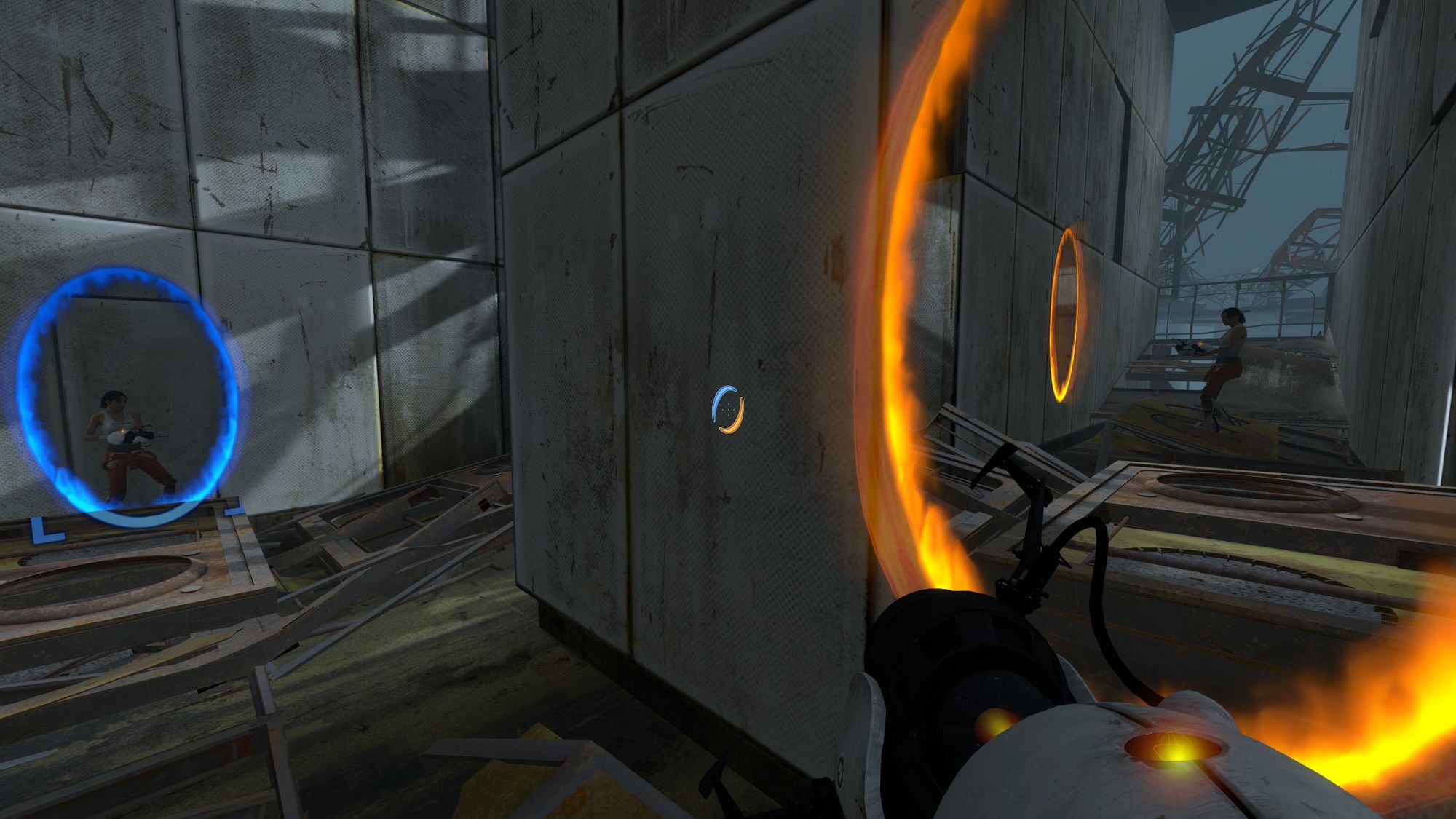
A render target view is encapsulated by the ID3D11RenderTargetView interface. This view is bound to the output merger stage and it points to a texture resource on the GPU. This view allows the output merger to write the pixels that it has assembled into a texture. If this texture was one of the back buffers of the Swapchain (which will be discussed soon) then we can present that texture to the screen as our output frame. Additionally, we can use this texture in the pipeline and apply it to objects in the scene. By being able to render to a texture and utilize it later we can create effects like mirrors, see through portals, in game displays, mini maps, etc. This effect can be seen in the games Portal and Portal 2 by Valve Corporation. This effect is so delicious and moist.
Portal 2
Depth Stencil View
The Depth Stencil View is extremely similar to a Render Target View in that it binds a shader that is 'rendered' too. The texture doesn't get filled with colour data but rather with depth information that can be used for occlusion of geometry among other things. (If two primitives occupy the same screen space we check the depth of each of them and draw the primitive that is closer). This view is encapsulated by the ID3D11DepthStencilView interface.
Shader Resource View
The Shader Resource View or SRV for short is used to bind textures and buffers to the shader stages of the pipeline for read only access. For example if we wanted to texture a model we would have to create a shader resource view that points to that texture resource. We would then bind that view to the pixel shader and then read data from that texture. The interface for the shader resource view is ID3D11ShaderResourceView
Unordered Access View
Unorded Access Views (UAVs) are similar to SRVs in that they bind resources to shaders but more specifically they bind to pixel shaders and compute shaders. (A general purpose for shader program for GPGPU operations.) The difference lies in the fact that UAVs allow for random read and write access to the resource. UAVs are encapsulated by the ID3D11UnorderedAccessView interface.
The Swapchain
The Swapchain is a relatively simple concept, it a series of buffers (textures) that are written to and presented to the window. While one buffer is being presented we're writing to the second buffer known as the back buffer. Originally, games and other applications only used a single buffer, this had an immersion breaking problem though. The problem was that the buffer could be drawn to the screen as it was being written to from the GPU. Unfortunately, this meant that the user could see the scene being drawn to the screen piece by piece.
Currently we use at least two buffers which are are constantly swapping, hence the name swapchain. We're never writing to the buffer that is currently being display to the screen. In Direct3D swapchains are encapsulated with the IDXGISwapchain interface. To draw to the back buffer of the swapchain we utilize a render target view that points to the texture resource of the back buffer. When we're done rendering we simply call the IDXGISwapchain::Present() method which swaps the buffers.
Although you don't technically need a Swapchain for a Direct3D application, you do need to create a Swapchain if you intend to create any sort of interactive or real-time application. About the only time you don't utilize a Swapchain is if you intend to never display but rather save images to the disk. Normally this is used for generating cinematics. Cinematics in video games are typically created using applications like Autodesk Maya or Autodesk 3DS Max or occasionally the open source application blender. These applications are often entirely ray-traced rendering which produce absolutely stunning results but at a very slow pace (potentially minutes, hours or even days for a single frame). Game developers are starting to utilize their game engines rendering capabilities to produce cinematics that are closer to what their games look like. In this manner you can also crank the render fidelity since real-time/interactive frame rates are not necessary.
Conclusion
In this post we have discussed the various layers that comprise an application that uses Direct3D. We seen that we have two APIs at are disposal which are DXGI and Direct3D 11. We looked at the graphics pipeline and the stages that comprise it. We examined the two primary resource categories being textures and buffers. We discussed how to access resources with resource views. Finally we discussed what the Swapchain is and why we need it to present to the screen.
With this information you can now comprehend how data is allocated, accessed and processed in a rendering application. This includes how each stage in the graphics pipeline affects the outputted image. In my next post we will examine how to program an application that renders a triangle to the screen.
Reference Material
Most of the content I have learned and subsequently presented to you is from three different sources. The first is Practical Rendering and Computation with Direct3D 11 by Jason Zink, Matt Pettineo, and Jack Hoxley (ISBN-13: 978-1568817200). The second source is Introduction to 3D Game Programming with DirectX 11 by Frank D. Luna (ISBN-13: 978-1936420223). The last source is the actual docs for Direct3D and DirectX found on MSDN. I've included many links to MSDN through out the post so that you can find more in depth information than what I provide.